
Engineering Lesson 11: Single board computers, sensors and data loggers
NEW: NEBP Tech Session 1: RFD900 and PTERODACTYL (January 2024) |
|
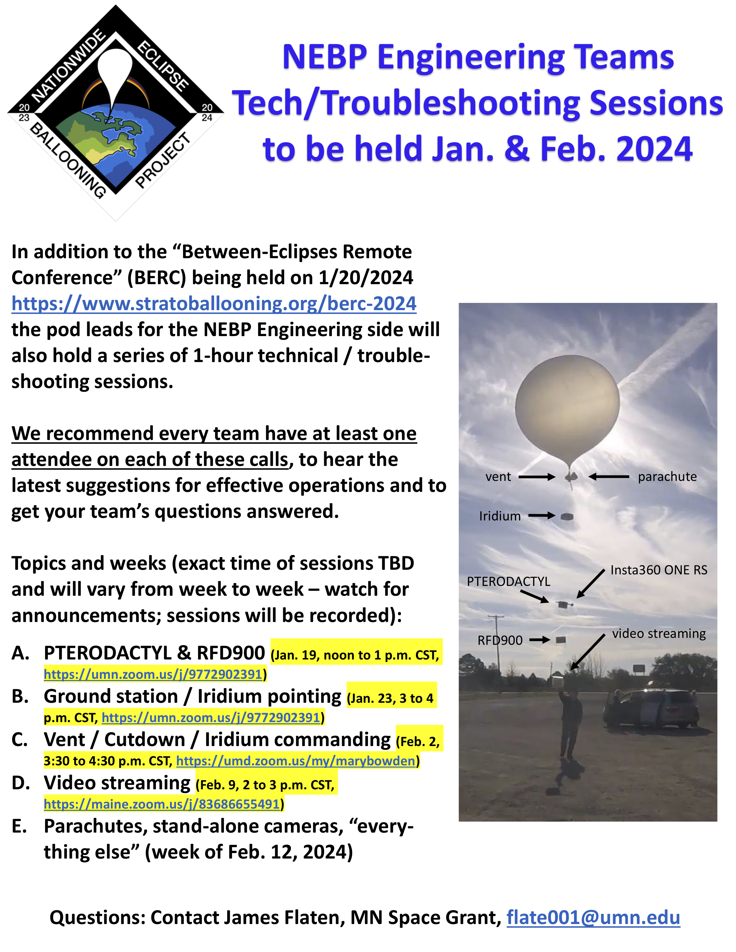 |
This National Eclipse Ballooning Project (NEBP) tech / troubleshooting session was recorded on Jan. 19, 2024 and gives useful information about RFD900 and PTERODACTYL flight computers. RFD900 troubleshooting slide deck [PDF - download from NEBP Google Drive] PTERODACTYL troubleshooting slide deck [PDF - download from NEBP Google Drive] (Click on flyer image for larger version with all dates and topics) |
Overview of the content
This lesson will include an overview and discussion of the RFD900 Atmospheric Sensor Suite with Telemetry. You will access data from GPS, pressure, temperature and accelerometer sensors; learn how to interpret values recorded in real units; and practice calibration. Additionally, you will learn how to build the PTERODACTYL flight computer -- “Payload To Enable Recording Of Data And Communication Telemetry Y (While) Lofted”
- NEW Jan 2024: NEBP Tech Session 1 - RFD900 and PTERODACTYL
NOTE :A new folder of engineering resources was posted 5/9/23 and includes
- 3D print files: Cutdown, PiCam, RFD900, Vent
- Ground station code (the folder contains a zipped file and the main .exe)
- Raspberry Pi video system: Instruction manuals and Ubiquiti Radio Config files
- RFD900
Learning objectives
After completing this lesson, students will be able to:
- Operate RFD900 Atmospheric Sensor Suite with Telemetry
- Operate PTERODACTYL (new folder of materials posted 4/5/23)
- Describe sensors setup
Contents
RFD900 atmospheric sensor suite with telemetry
NEBP Tech Session 1: RFD900 and PTERODACTYL (January 2024)
This National Eclipse Ballooning Project (NEBP) tech / troubleshooting session was recorded on Jan. 19, 2024 and gives useful information about RFD900 and PTERODACTYL flight computers. [YouTube video - 59:58]
RFD900 Programming Instructions: Programming the RFD900 Custom Board From Borealis Labs
By Matthew Phillips
You can also download the instructions as a PDF document in regular print and large print (same as the HTML text beloww)
- RFD900 Programming instructions by Matthew Phillips [PDF, included as alternate download]
- Large Print RFD900 Programming Instructions by Matthew Phillips [PDF, included as alternate download]
The following instructions are very much aided by documentation made by Silicon14 on Instructables.com (https://www.instructables.com/ATMEGA2560-Standalone-Using-Arduino-UNO/); however, I found the instructions insufficient for this specific use case of the ATMega2560 and is therefore the reason for this document.
Parts:
Firstly, you will need a few parts.
- RFD900 Custom Board
- Arduino Uno Board
- USB to USB type B for Arduino Uno
- 6 Male to Female wires to connect to board pinouts
- A computer
Setting up the Arduino Uno:
To start off with, please make sure you have the Arduino IDE installed on your computer, if it is not you can find it here: https://downloads.arduino.cc/arduino-1.8.19-windows.exe
Installing IDE Library
We now need to install a library for the ATMega2560, the MegaCore library. To start off with, let’s open the Arduino IDE and go to File --> Preferences and paste in:
https://mcudude.github.io/MegaCore/package_MCUdude_MegaCore_index.json
into the Additional Boards Manager URLs. Now we can install the library, which will be under tools --> board --> boards manager. From there you can search for MegaCore and install the library.
Uploading The Programmer Code
Now we’re on to setting up the Arduino Uno board to act as a programmer for the ATMega2560 Microprocessor that is on the RFD900 board. To do so, plug in the Arduino Uno to your computer and “Connect just the Arduino UNO and load the File -> Examples -> ArduinoISP sketch. Select the Arduino UNO board under Tools and the default AVRISP mkII as programmer. Select the serial port (under tools-->ports-->arduino uno port) and finally compile and upload the sketch as you would normally do.” (Silicon14). This just sets up the Arduino Uno so it may act as the programmer for the ATMega2560 on the RFD900 board.
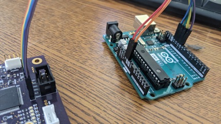
From here you will want to disconnect the Arduino Uno and connect the RFD900 Board to the Uno with the following pinout:
UNO pins -> ATMEGA2560 pins
10 -> reset
11 -> MOSI
12 -> MISO
13 -> CLK
5v -> 5V
GND -> GND
(Above format credited to Silicon14)
Burning the Bootloader:
Editing Board Config File
“Once done with the connections, now find a file called "boards.txt" in your Arduino installation directory.
In my case, the path is "C:\Program Files (x86)\Arduino\hardware\arduino\avr".
Open it with a text editor [as administrator] (I used Notepad++) and locate to the ATMEGA2560 section. Find the line "mega.menu.cpu.atmega2560.bootloader.high_fuses=0xD8"
We have to replace the value of "0xD8" with "0xD9". This is so, because in stand-alone ATMEGA2560 chips, if the BOOTRST fuse is not set, the chip will be correctly programmed, but the programs will never run. So the line could look like this (we can keep the original line commented as I did.)
"mega.menu.cpu.atmega2560.bootloader.high_fuses=0xD9".
Save the changes and close the text editor.” (Silicon14)
Configuring
Now we can get all of our options out of the way. In boards we will want to go into the newly added MegaCore boards and select ATmega2560. Then we’ll set the following under tools:
Clock --> “External 16 MHz”
BOD --> “BOD 2.7V”
EEPROM --> “EEPROM retained”
Compiler LTO --> “LTO disabled”
Pinout -->Arduino MEGA pinout
Bootloader --> “UART0”
Port --> whatever port the Arduino Uno is on (At this point you can plug the Arduino Uno back in)
Programmer --> “Arduino as ISP”
Burning
Now we can go up to tools --> Burn Bootloader
Programming:
Installing Libraries
Assuming that you are using the default software to collect data with the board, you will need to install a few libraries for the default code to work. All these libraries can be searched for, and installed, by going to sketch--> include libraries --> manage libraries. Those libraries are:
SparkFun u-blox Arduino Library
MS5xxx
Adafruit_LSM303_Accel
Adafruit_LIS2MDL
Editing config files
For the RFD900 board to communicate with the SD card and properly write to it, we also must edit a config file due to a mismatch in read/write speeds by default. So please open notepad as an administrator again and go to the directory:
C:\Users\<Username>\AppData\Local\Arduino15\packages\MegaCore\hardware\avr\2.1.1\libraries\SD\src
From there open SD.cpp and change the following:
Original code
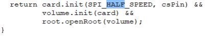
Edited code
Uploading
Finally, we can now upload our code. To do so, please have your code ready and do Sketch --> Upload Using Programmer. You must upload using programmer, otherwise it will not upload the program correctly to the board. Once uploaded there should be two LEDs that begin to blink every few seconds that are labeled on the PCB to be D12 and D13. If these are blinking, we know that it is collecting data and storing it to the SD card. We can also check for a file on the SD card named PAYLOAD
RFD900 Balloon Telemetry senior capstone project
RFD900 Balloon Telemetry Senior Capstone Final Project Report – Martinsen, Bachman, Valentino-Manno. [download from NEBP Google Drive folder]
Montana Space Grant Consortium’s (MSGC) BOREALIS (balloon outreach research exploration and landscape imaging system) flies high-altitude balloons that require live streaming to a ground station antenna. The balloon payload lacks a small, reliable, lightweight sensor suite with low power consumption. A group of capable engineers was recruited to design a complete payload that collects data during flight and transmits the data back to the ground. This system collects GPS, temperature, pressure, orientation, acceleration, and time data. The data is then saved and sent to the engineers’ ground station where it is saved again and displayed. It meets physical constraints and incorporates a custom printed circuit board with a programmed microcontroller.
RFD900 Balloon Telemetry Final Design Review and Overview (presentation by Martinsen, Bachman, Valentino-Manno)
- Download as PPT slides from NEBP google drive folder
- Download slides as PDF from NEBP google drive folder
RFD900 Instruction manual
You can also download this as alternate PDF files
- RFD Instruction Manual [download from NEBP Google Drive folder]
- RFD Instruction Manual - large print [download from NEBP Google Drive folder]
This document contains steps on downloading the board manager, libraries, specific library changes that are necessary and important calibration steps. Once completed, an external Arduino uno may be used to program the board.
- Setting up the MegaCore Board Manager
- Begin by downloading the MegaCore board manager
- Download link: Github
- Select the ATmega2560 in Arduino under Tools>Board
- Downloading Libraries
- Navigate to the Arduino library manager by going Tools>Manage Libraries
- Search for and download the required libraries
- Editing Libraries
In order to achieve functioning data storage, the MegaCore’s SD card library needs to be edited
- Go to where the library is located
- For example:
C:\Users\<Username>\AppData\Local\Arduino15\packages\MegaCore\hardware\avr\2.1.1\libraries\SD\src
- Open the SD.cpp file
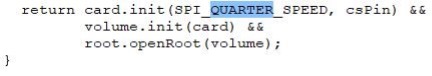
- Make the following change (HALF -> QUARTER)
Original code
insert rfd4here
Edited code
insert rfd5 here
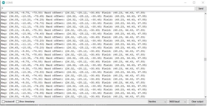
- Calibrating the Magnetometer
- Download the “Adafruit Sensor Lab” library
- Open up the mag_hardiron_simplecal example
- File>Examples>Adafruit Sensor Lab>calibration>mag_hardiron_simplecal
- Upload the code to the device
- Spin the magnetometer board until the final three values settle near one another (values should not exceed 65uT)
- Once settled, compensate each magnetometer reading by the values obtained from the middle three values, by adding each offset value to the appropriate reading
Example output of calibration program
PTERODACTYL Flight computer
- Introduction to PTERODACTYL Flight Computer by Dr. James Flaten, Minnesota Space Grant Consortium [YouTube video, 11:32, closed captioned]
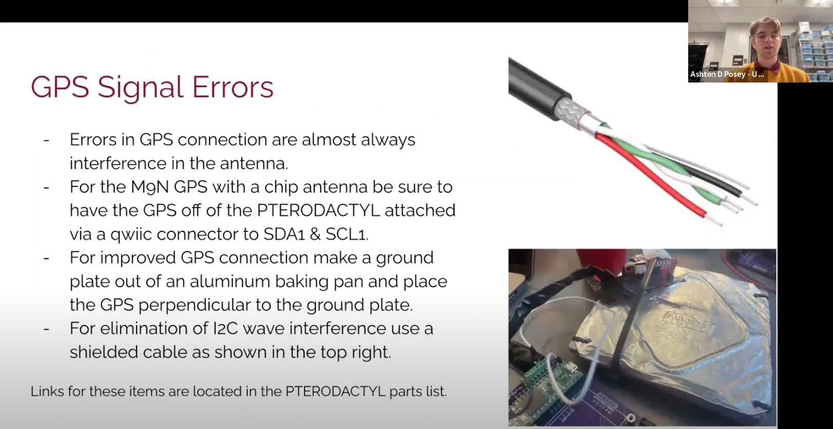
- NEW: Posted 5/24/23 -- PTERODACTYL GPS modifications video - The video explains how to put the GPS module "off-board" and talks through some of the latest OLED screens. Created May 2023 by Minnesota Space Grant Consortium
-
PTERODACTYL FolderNEW: posted 4/5/23.
- PTERODACTYL Code - a folder containing all Arduino libraries required to run the PTERODACTYL and documentation for how to download them.
- PTERODACTYL Power Plane - Files to order/print the PTERODACTYL Power Plane PCB.
- PTERODACTYL v3.6 Build Photos - This resources shows all the parts needed to build the PTERODACTYL, along with step-by-step instructions
- PTERODACTYL v3.6 PCB Files - Files to order/print the v3.6 PTERODACTYL PCB.
- Intro to PTERODACTYL Video - A video outlining the Intro to PTERODACTYL Slides.
- Introduction to PTERODACTYL MnSGC Ballooning - A slide deck outlining the parts used on the PTERODACTYL and how to use the device.
- PTERODACTYL v3 Parts List - Excel file with all the parts used in the PTERODACTYL.
- PTERODACTYL v3.6 Photo Build Slides - Slides showing how to build the PTERODACTYL.
- Purple XBee Set Up - Document outlining how to configure the Purple XBee 3 using XCTU
Sensors
Below are links to the datasheets for the sensors
bq32000 real-time clock data sheet (Texas Instruments - external link)
lmt84 analog temperature sensors data sheet (Texas Instruments - external link)
lm87 AnalogTemperatureSensorsWith Class-ABOutput data sheet (Texas Instruments - external link)
lsm303agr data sheet (STMicroelectronics - external link)
tmp116 DigitalTemperatureSensor data sheet(Texas Instruments - external link)
![]() Don't forget to track today's progress in your portfolio
Don't forget to track today's progress in your portfolio
Will you take a few minutes to give us some feedback on this lesson? Thank you!
Course home page // Next lesson >>