
Engineering lesson 14: Radios and antennas on the payloads and ground station
This lesson covers the technical engineering systems used to safely and successfully capture real-time video and data from a high-altitude weather balloon during the October 14, 2023 annular eclipse and the April 8, 2024 total solar eclipse.
Hardware/systems covered in this lesson include:
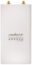
- Rocket M2 2.4 GHz or Rocket M5 5.8 Ghz
- Ground station dish antenna
- grid antenna for RFD900
- PCB antennas for XBEE
- Omni antennas for video streaming
This lesson also covers what Internet access is required during a launch for streaming data and balloon tracking. Hardwire is recommended; a hotspot might be possible (but video may be choppy). During an eclipse, wireless internet may be degraded.
Learning objectives
After completing this lesson, students will be able to:
- identify the major components of each engineering payload system.
- demonstrate the assembly and operation of each payload system.
- describe the need for internet availability and explain which systems require internet access.
Content
Information on this page falls into these sections:
Internet and Antennas

This presentation offers a complete overview of the engineering Internet requirements and RF payload inventory for the NEBP engineering teams.
Download the same presentation as a PDF [from our NEBP Google Drive. Posted 4/23/23]
Ground station laptop
COMING SOON
Ubiquiti Radio
View the entire Ubiquiti Radio setup manual as a PDF document [alternate download; same as below]
A pair of Ubiquiti radios will be configured to become a transparent bridge to connect the ground station and the payload. The Ubiquiti radios acts as a long wireless ethernet cable between two points. This document will describe the configuration process and required equipment to create a working transparent bridge.
Equipment needed
- A pair of Rocket M5 Ubiquiti radio (Or similar model but this document is best for Rocket M5 Ubiquiti radio)
- 4 ethernet cables (Straight-Through)
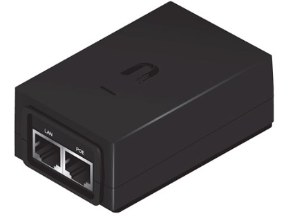
- 2 Ubiquiti power boxes with its power cable
- Antennas for both radios
Basic Setup
The following steps will prepare the Ubiquiti radios for long distance connection. Skip to Advance Setup section to allow the Ubiquiti radio to be connected to a router.
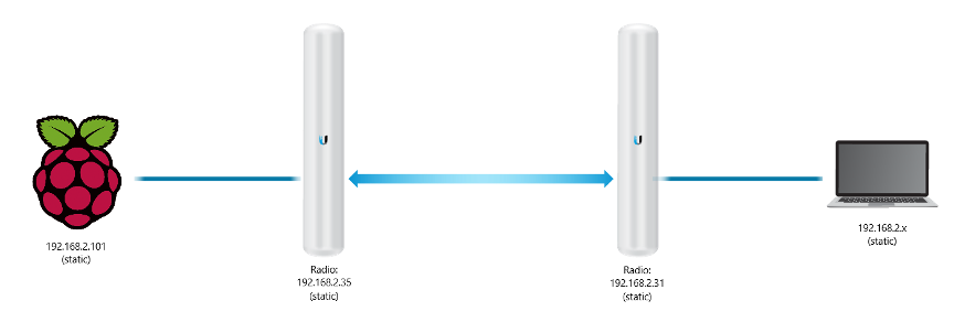
The radio connected to the computer will be called the Ground Station Radio and the other radio connected to the Raspberry Pi will be called the Payload Radio.
Computer Setup
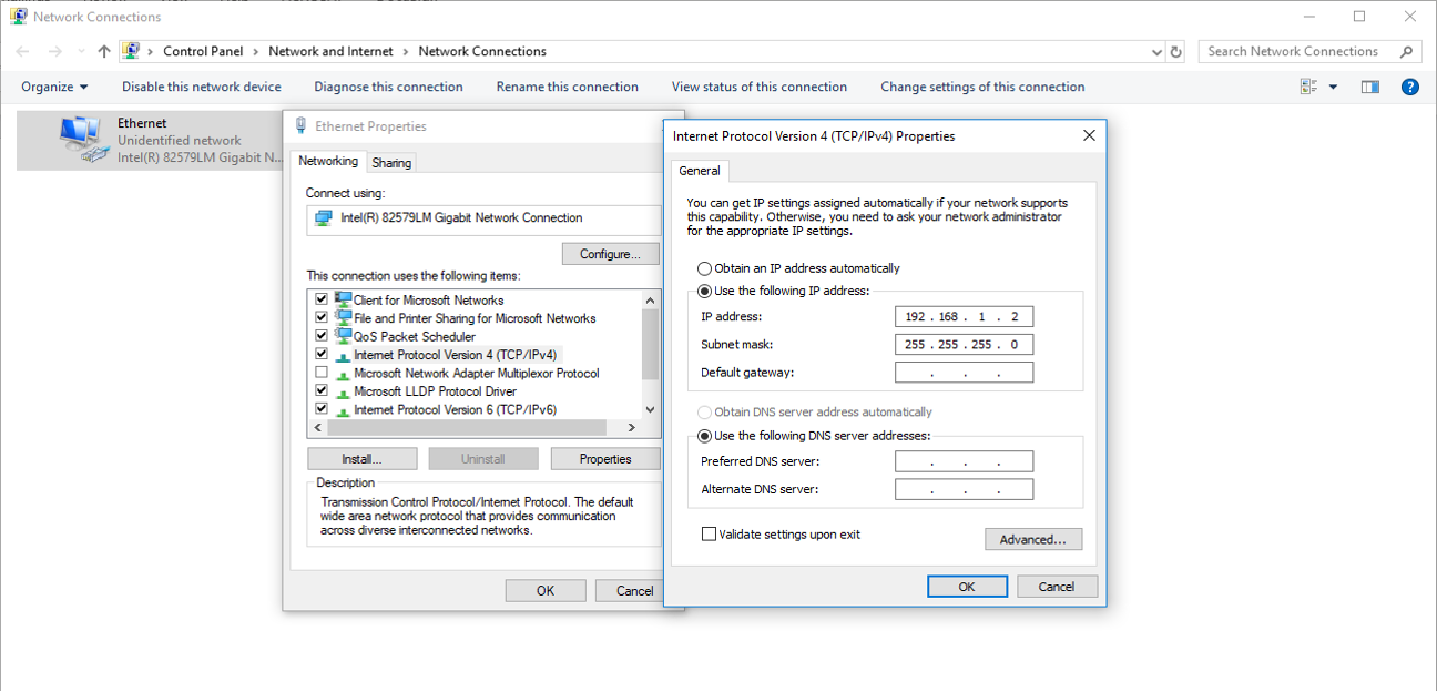
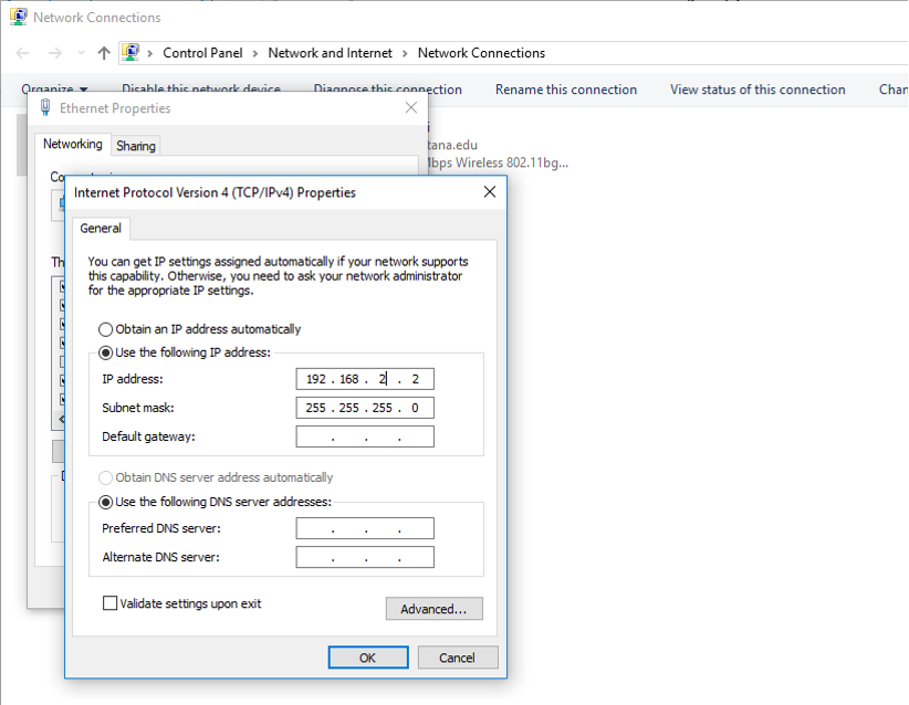
In order to setup the Ubiquiti Radio for the first time, the user must configure their computer to have a static IPv4 address set to 192.168.1.x in their ethernet port. This configured computer will be used to change the settings of the Ubiquiti radio.
Ubiquiti Radio connection for Ground Station and Payload
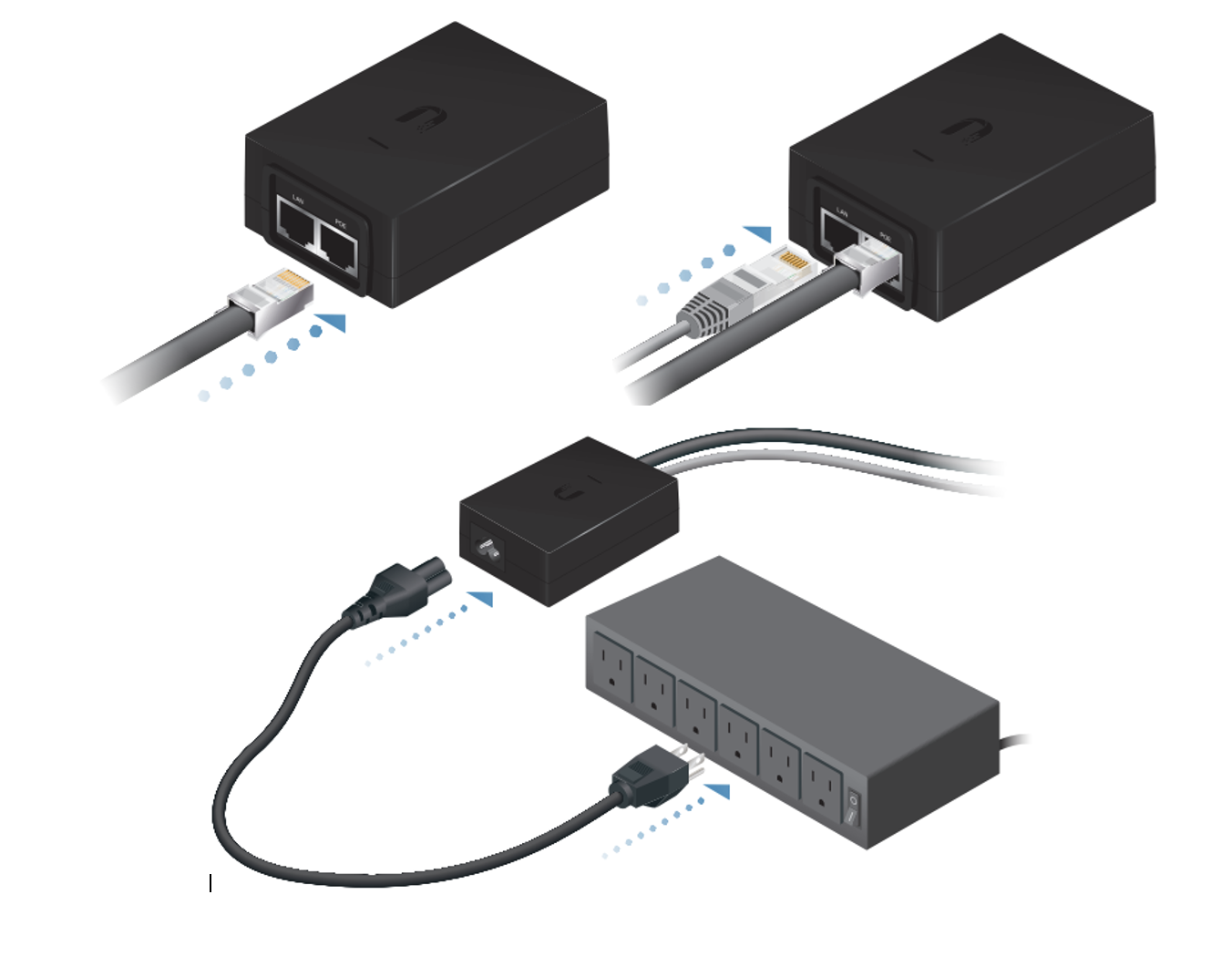
The computer is now prepared to configure the Ubiquiti Radio, the Ubiquiti Radio needs to be powered and connected to the computer. First, connect an ethernet cable from the Ubiquiti Radio to the power box’s port labeled POE. Then, another ethernet cable is connected from the configured computer to the power box’s port labeled LAN. The power box can then be plugged into a wall. Two yellow LED should light up on the Ubiquiti Radio.
Accessing Radio’s Configurations
Ubiquiti Radio’s settings can now be accessed. Open a web browser like Google Chrome or Firefox and then go to http://192.168.1.20 (make sure its http, not https). The first time will show a screen of unsecure network, allow the site and should show a first-time setup screen.
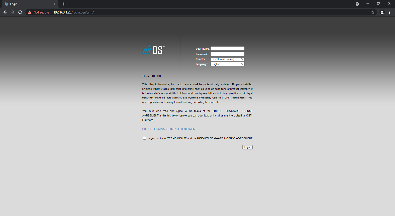
Enter the login information (By default, username: ubnt password: ubnt). Enter United States and English for the other two. Tick the agreement to continue to login.
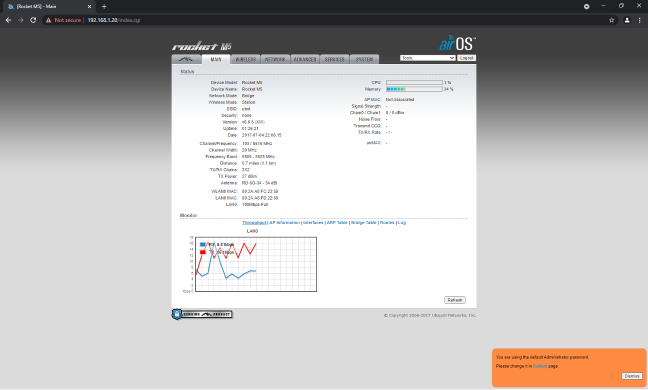
After login, the screen should look like the following:
Changing Ubiquiti password
Go to the System tab and click on the key next to the user name. Enter the current password, new password and the new password again. Click Change and click Apply when the blue bar appears.
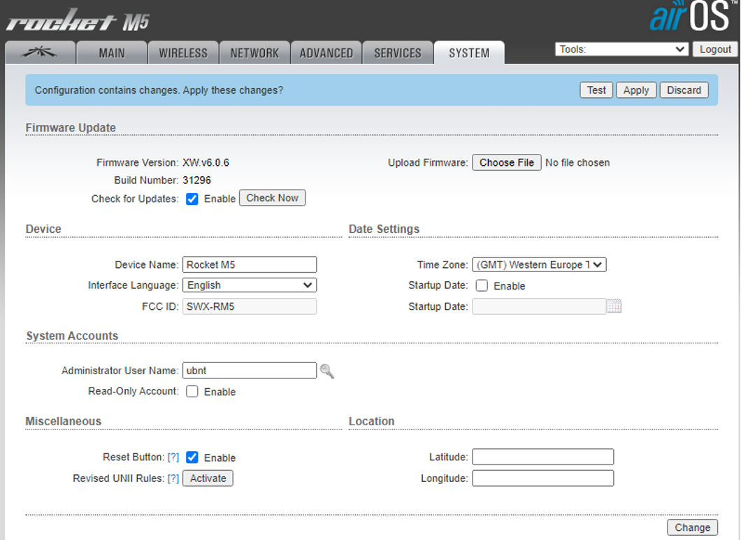
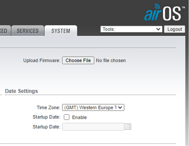
Changing Time Zone
Go to the System tab and change the Time Zone to your time zone. This could help with logs.
Picking and Assigning the Ground Station SSID
One of the Ubiquiti radios is assigned to the Ground Station Radio. It is highly recommended to label the radio accordingly to avoid confusion.
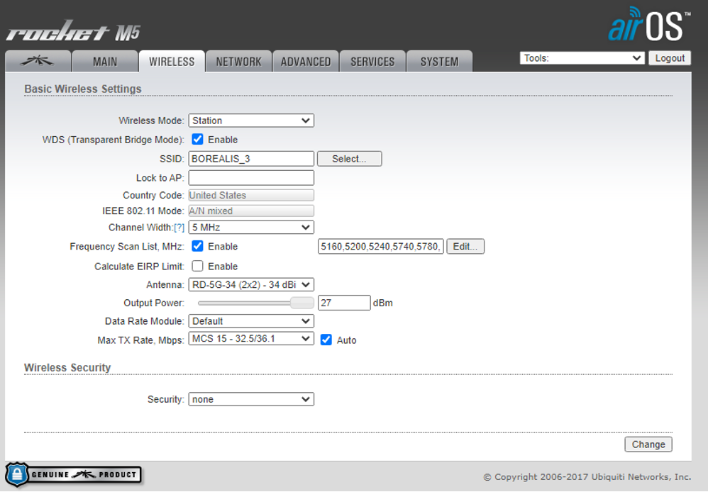
Go to the Wireless tab, Change the Wireless Mode from Station to Access Point. Tick the checkbox next to WDS (Transparent Bridge Mode). In the textbox next to SSID, enter an appropriate name that the pair of radios will use to connect to each other. Change the Channel Width to 5Mhz. Tick the checkbox next to Frequency List, Mhz and then enter the following: 5160,5200,5240,5740,5780,5820. The following is a list of frequency allowed to be used in US. Please check with the local area for allowed frequencies. Make sure the check box next to Max TX Rate, Mbps dropdown is checked. After the changes, the screen should like the following:
Click Change and then click Apply once the blue bar appears
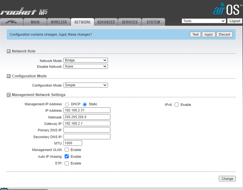
Assigning the Ground Station Radio with an IP address
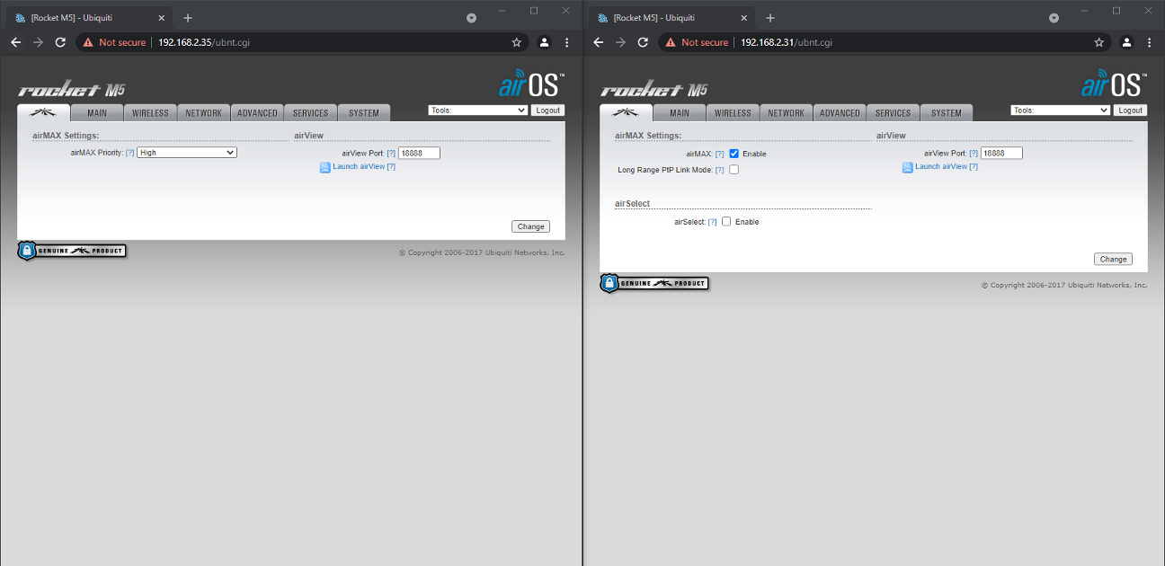
Go to the Network tab, change the IP address from 192.168.1.20 to 192.168.2.31. Change the Gateway IP from 192.168.1.1 to 192.168.2.1. Click Change and then click Apply once the blue bar appears. You will NOT be able to access the configuration through 192.168.1.20 anymore instead it will be the newly assigned IP (192.168.2.31). Accessing the site will require changing the configured computer’s IP, which will be done later.
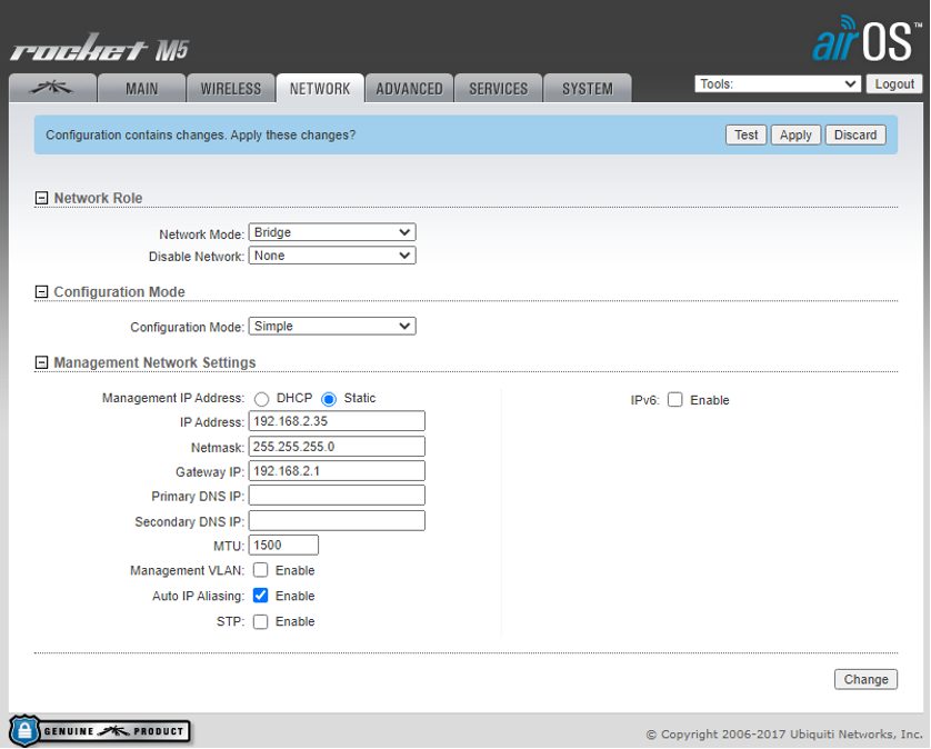
Assigning the Payload Radio
Before proceeding to this step, make sure to do the same steps from Accessing Radio’s Configurations to Changing Time Zone for the Payload Radio.
Go to the Network tab, change the IP address from 192.168.1.20 to 192.168.2.35. Change the Gateway IP from 192.168.1.1 to 192.168.2.1. Click Change and then click Apply once the blue bar appears. You will NOT be able to access the configuration through 192.168.1.20 anymore instead it will be the newly assigned IP (192.168.2.35). Accessing the site will require changing the configured computer’s IP.
Changing the Configured Computer’s IP
Changing the configured computer’s IP is changed again to be able to access the Radio’s configuration. Same steps in Computer Setup section, the IP is changed from 192.168.1.2 to 192.168.2.2.
Connecting the Payload Radio to the Ground Station Radio
Go to the Wireless tab, Change the Wireless Mode from Station to Station. Tick the checkbox next to WDS (Transparent Bridge Mode). In the textbox next to SSID, enter the SSID assigned to the Ground Station Radio. Change the Channel Width to 5Mhz. Tick the checkbox next to Frequency List, Mhz and then enter the following: 5160,5200,5240,5740,5780,5820. The following is a list of frequency allowed to be used in US. Please check with the local area for allowed frequencies. Make sure the check box next to Max TX Rate, Mbps dropdown is checked. After the changes, the screen should like the following:
Click Change and then click Apply once the blue bar appears.
If all the steps were followed correctly and both radios are powered, the other 4 LEDs on both the radios should light up. Both radios can now be accessed from either side by entering their assigned IP address.
Optimizations
The following steps will help the Ubiquiti radios work to its full potential which could result to better bandwidth and further distance communication.
Firmware Update
By updating the firmware, the radios could receive additional settings and receive optimization from the company.
Make sure that the computer has internet access by connecting to Wi-Fi. If this cannot be done, then skip this section and go to Uploading Firmware section.
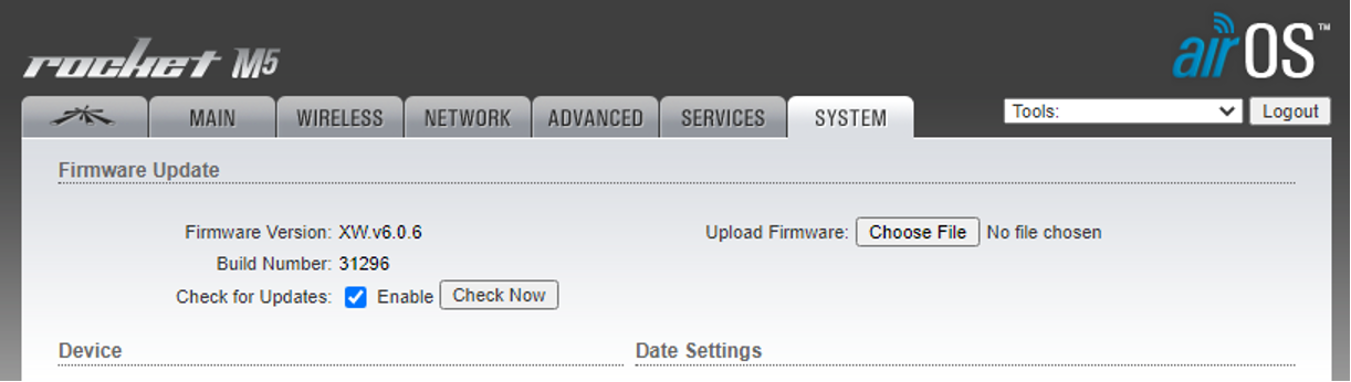
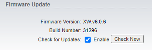
Go to System tab, Click Check Now button next to Check for Updates. If it fails, skip this section and go to Uploading Firmware section. This maybe due to Firmware being too old.
Due to Firmware Update, the Time Zone may have change. Make sure to change it to the appropriate timezone.
Uploading Firmware
If the option of connecting to Wi-Fi while tethered to the Ubiquiti is not available, uploading the updated firmware is possible.
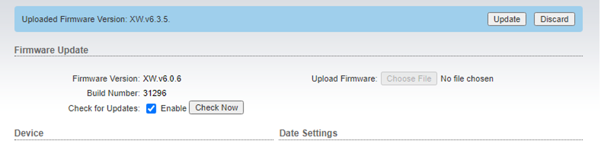
Before disconnected from the Radio, take note of the Firmware Version:
While connected to the Internet, go to https://www.ui.com/download/.
Since this manual is optimized for Rocket M5 radios, the firmware download can be found from clicking dropdown airMax® M Series, then Rocket® M, then M5
Download the latest firmware version with the same board type
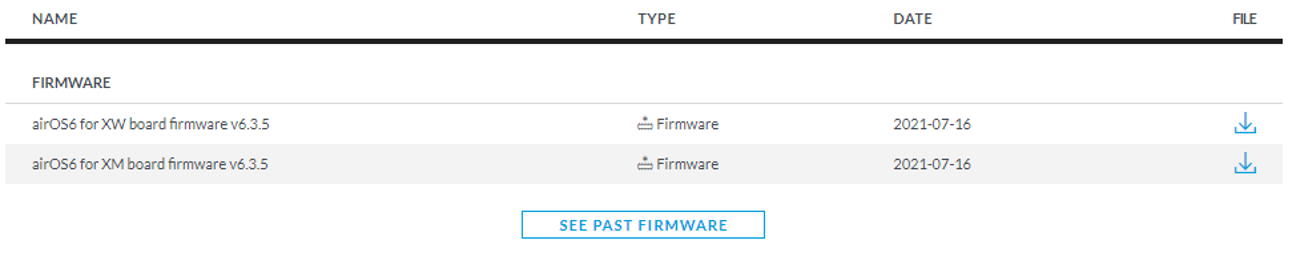
Click I Accept when the popup appears then click Download File button.
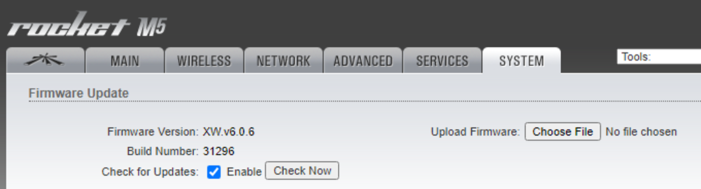
Connect to the Ubiquiti Radio. Upload the firmware by going to System tab and clicking Choose File button next to Upload Firmware
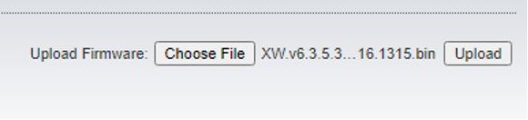
Choose the recently downloaded firmware file and click Open.
Click Upload when it shows
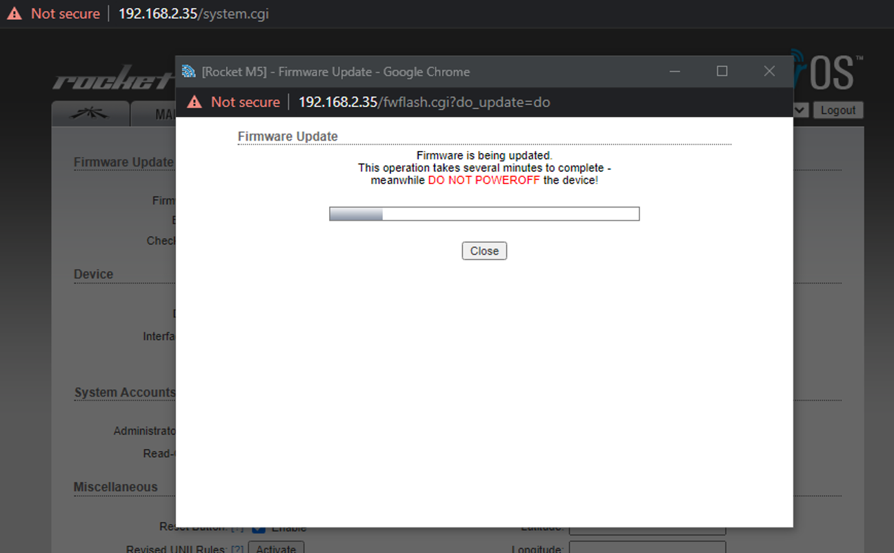
When the blue bar appears, click Update
The update will take time. DO NOT POWEROFF.
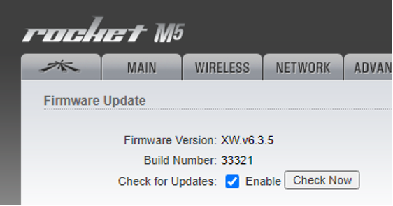
Check if the firmware has been successfully updated by going to System tab again
Additional Settings changes
Both the payload and ground station radios were configured to use the default antenna. Depending the on the antenna chosen, the output power of the communication changes.
By checking the datasheet of the antenna used, an exact “dBi” can be found. For example, the RD-5G-30 was found to have 30 dBi which results to a maximum 23 dBm output power with
![]() Don't forget to track today's progress in your portfolio
Don't forget to track today's progress in your portfolio
Will you take a few minutes to give us some feedback on this lesson? Thank you!
Course home page // Next lesson >>