
Engineering Lesson 8: Payloads and groundstations
This lesson includes detailed instructions for the ground stations and tracking stations.
See also Lesson 12 for more information on photo and video camera systems, including new files posted September 2023:
- box for Pi Camera and for RFD900 Iridium data logger and
- 3D printing a case for Insta360 camera and extra battery
NEBP Tech Session 2: Ground Stations and Iridium Tracking (January 2024) |
|
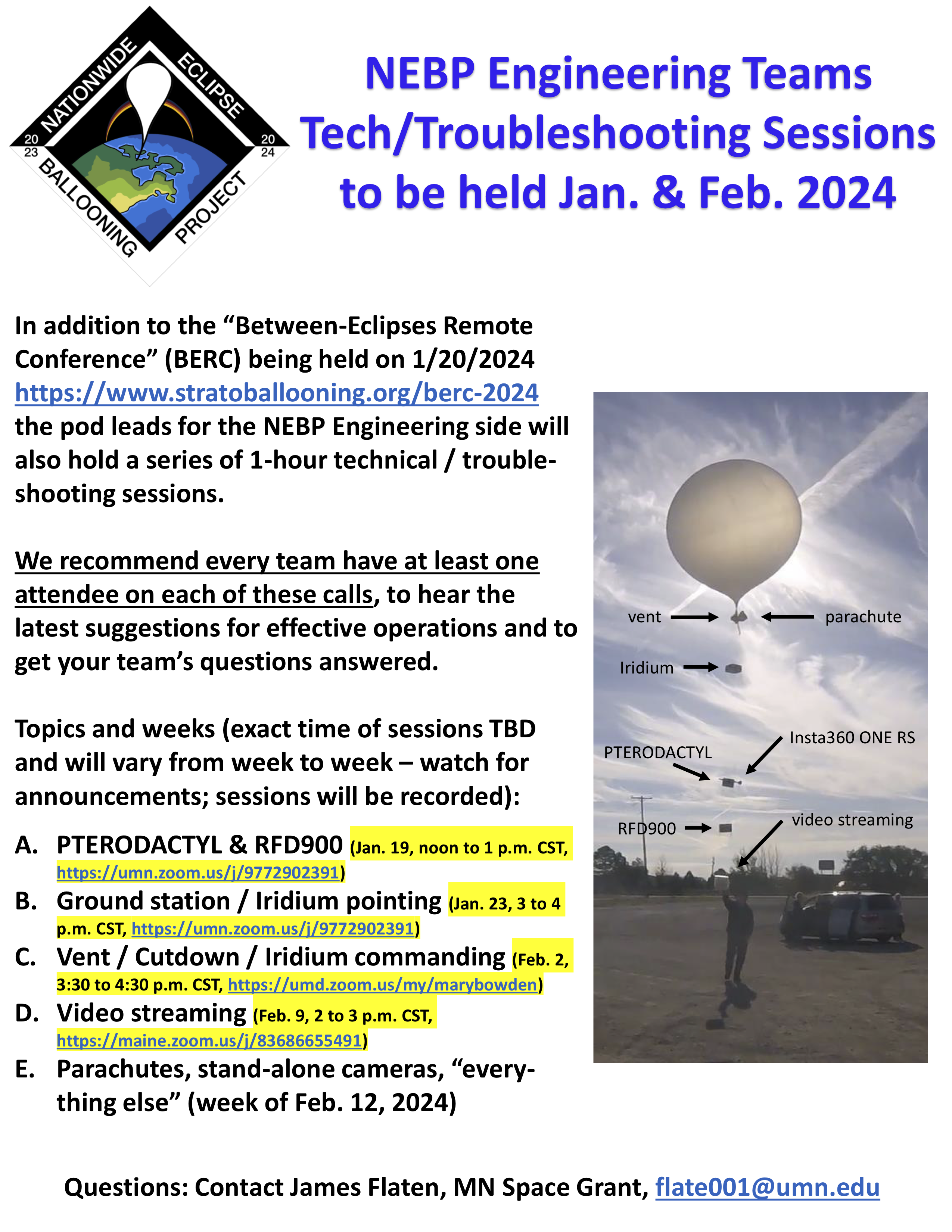 |
This National Eclipse Ballooning Project (NEBP) tech / troubleshooting session was recorded on Jan. 19, 2024 and gives useful information about ground stations and iridium tracking. (Click on flyer image for larger version with all dates and topics) |
NEBP Tech Session: Parachutes, stand-alone cameras and more (February 2024) |
|
 |
This National Eclipse Ballooning Project (NEBP) tech / troubleshooting session was recorded on Feb. 16, 2024 and gives useful information on parachutes, stand-alone cameras and more. (Click on flyer image for larger version with all dates and topics) |
Overview of the content
For official NEBP teams, the Polulu and Arduino you receive are already programmed. The tracking software .exe was sent in Spring 2023. If you need anything else or have questions, please contact your pod lead. Thanks!
NOTE: A New folder of resources posted on 5/9/23 includes:
- 3D print files: Cutdown, PiCam, RFD900, Vent
- Ground station code (the folder contains a zipped file and the main .exe)
- Raspberry Pi video system: Instruction manuals, Ubiquiti Radio Config files
- RFD900
Contents
See Lesson 11 for an Overview of the RFD900 ground station
- Flight line test results
- NEW info 9/22/23: Parachute packing
- Mechanical design of flight boxes
- Tracking station assembly and wiring video
- Ground station wiring schematic
- Pololu driver settings
- Ubiquiti Radio Set-up Guide
Flight line test results
BOREALIS Flight Line Test Results [download from NEBP google drive]
Parachute packing and recovery
How to pack a parachute, from the Montana State University BOREALIS team. [YouTube video]
We have flown this design twice now with two clean chute deployments. This is modeled after emergency reserve parachutes. It builds on the ideas that Rick shared with his parachute packing. Take the time to pack it right and it should open clean every time.
- NEW 9/22/23: Diaper/Pull-Up Instructions (Packed Air Management Parachute Ensured Recovery (AKA: P.A.M.P.E.R) from Montana Space Grant Consortium BOREALIS team [download from NEBP Google Drive]
- CAD files for download
Mechanical design of flight boxes
Files for the payload boxes: PDF and AutoCAD files for RFD Iridium Top, Bottom and Door [Download from NEBP Education Google Drive; posted 7/17/23]
Payload box building is more on the art side rather than engineering. They do need to be sturdy, recoverable, and take a 40 mph ground impact. Many designs will work. This document will share one version. A good place to start is with constraints for boxing and landing the payloads.
The University of Maine High Altitude Ballooning Team generally tries to reduce payload weight whenever possible and practical. As a result our boxes tend to be light. Because Maine has many water bodies, boxes need to float. As much as making the boxes waterproof would be nice, no box as of yet has kept all water out. Box design can help keep some water out but probably not all. Avoiding salt water landings is very important as it is very destructive to powered electronics.
Tracking station assembly
![]()
Tracking station assembly video - [YouTube video by Chad Dunbar, Montana Space Grant Consortium. 1:31:31. Closed captioned]
Tracking station wiring
Tracking Station Wiring Video - by Randy Larimer, Montana Space Grant Consortium [YouTube video, 24:40]
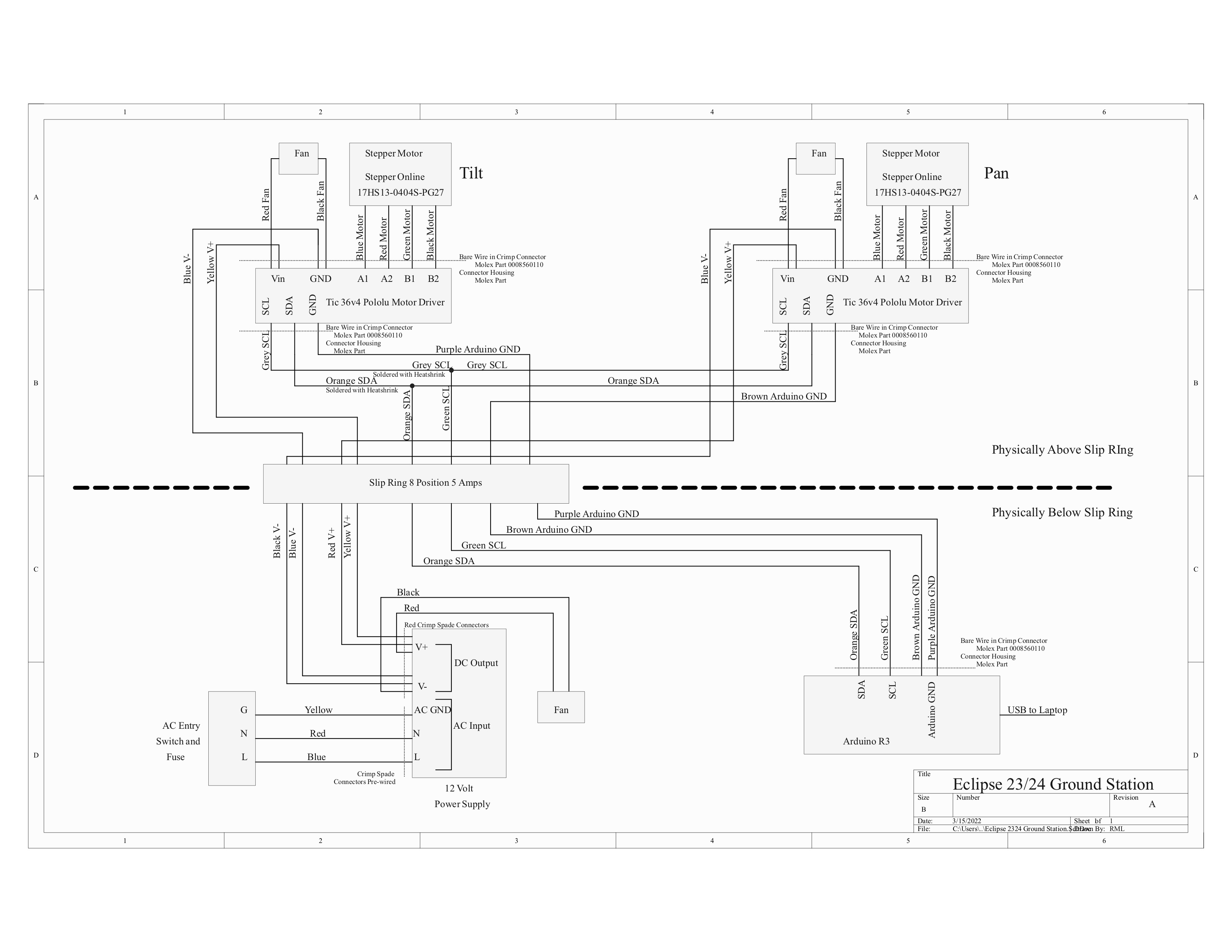
Ground station wiring schematic
See the diagram below and also this downloadable version
Pololu driver settings
You can also download the Pololu driver settings in PDF [same as HTML text below]
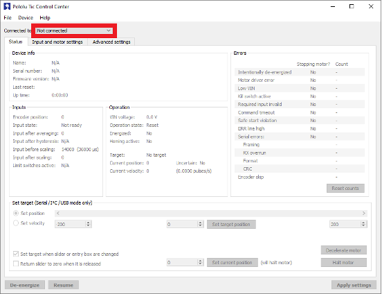
This requires the Pololu Tic Control Center and Tilt and Pan stepper motor configuration files. Plug in USB to Micro USB into the computer and open Pololu Tic Control Center.
There are two stepper motors in the ground station. One pointed down that controls the pan and the other on the side that controls the tilt. See Figure 1 Ground Station Stepper Motors.
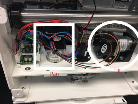
- Follow the wire from the stepper motor that controls the tilt to the motor controller (Figure 2). Connect the micro-USB to the motor controller.
- On the Tic Control Center, click on the dropdown on the top left of the window and select something like #01234567 T825. See Figure 2 Pololu Tic Center.
- Click on File on the top right of the window and then select Open settings file… and select the Tilt configuration. Click Apply settings at the bottom of the window.
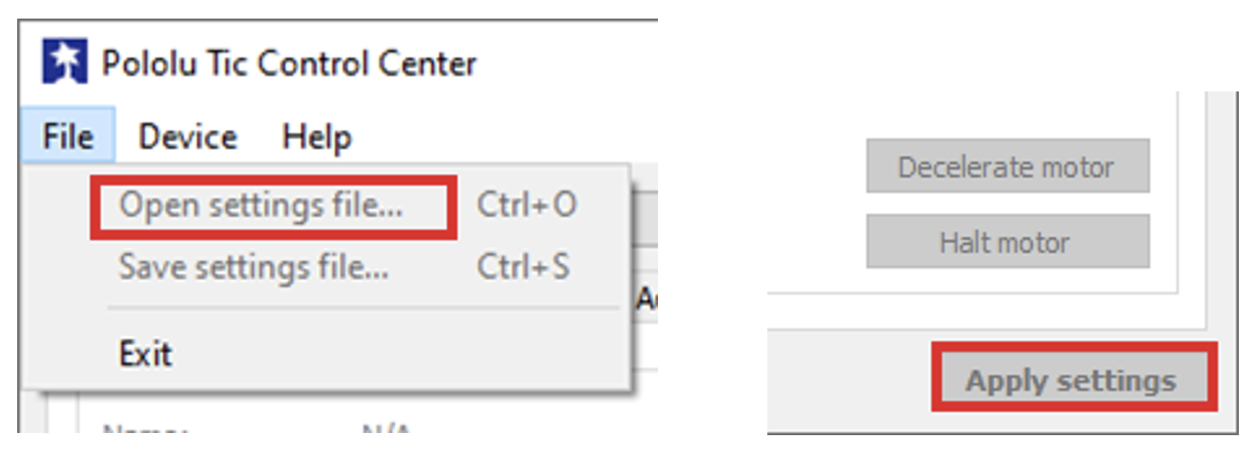
Figure 3 “Open settings file...” option and Apply settings button
- Repeat for the pan motor.
Ground Station (BRAD) Tracking Software Instructions
Written by: Mathew Clutter
You can also download these instructions as an alternate PDF [same content as below]
If you are reading this, you likely want to track a balloon using the Montana Space Grant’s BOREALIS program’s ground station. This document will lay out the steps to use the software associated with the ground station to track a balloon.
To launch the GUI, double click on the file called main.exe. This will launch the tracking software.
- Select or enter your Balloon IMEI in the top left corner
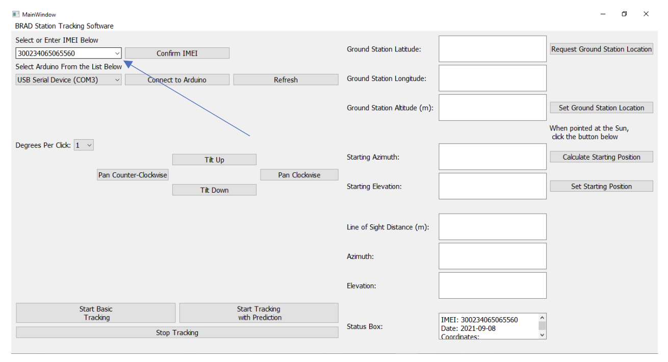
- After selecting your balloon’s IMEI, hit the confirm IMEI button.
- Ensure that the date in the status box in the bottom right corner is the correct date. If not, the balloon will not be tracked properly.
- Select and connect the Arduino in the box below the IMEI selection
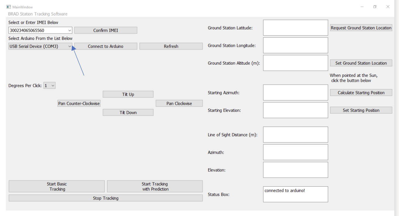
- Ensure that the Arduino connected to the ground station is selected and press the
“Connect to Arduino” button.
- If you have not yet connected the Arduino on the ground station, plug in the Arduino and then git the Refresh button. This will find the Arduino.
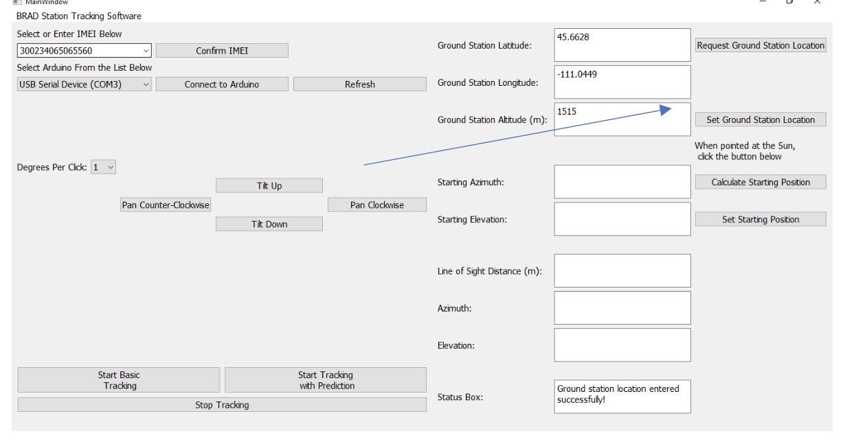
3.Obtain the GPS location of the Ground Station setup
-
- Enter in the ground station coordinates into the ground station location boxes.
-
- After obtaining/entering the location of the ground station, hit the “Set Ground Station Location” button.
4. Use the adjustment buttons to point the solar sight at the sun
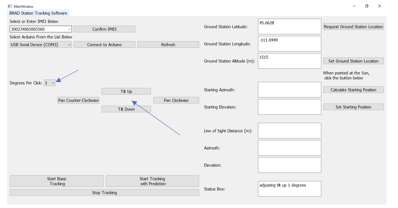
- Adjust the size of the motor movement using the “Degrees Per Click” box.
- Ensure that the sun is centered in the solar sight.
5. Set the starting position that the antenna is pointing at.
- Ensure that the ground station location is set and the solar sight is pointing at
the sun.
- In the event that the sun is not visible, do your best to estimate the azimuth and elevation that the ground station is pointed. It is recommended to use a compass to obtain the azimuth, and a level to set the elevation to 0. If using a compass, ensure that you are using true north, and not magnetic north. Many phone compasses will automatically calculate the declination for you, and give the reported position in terms of true north.
- Click the “Calculate Starting Position” button on the right side of the screen. (unless calibrating using compass and level)
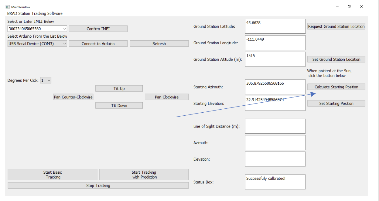
- Once the starting position is calculated, hit the “Set Starting Position” button.
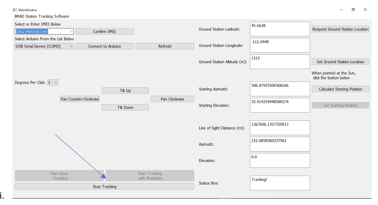
6. Hit the “Start Tracking” button in the bottom left to begin tracking the balloon!
- Basic tracking will simply point the antenna at the last position reported by the Iridium. Tracking with prediction will attempt a more precise tracking by extrapolating the change in position between previous Iridium pings, to continue adjusting the pointing of the antenna between pings of the Iridium.
- The “Stop Tracking” button will end the tracking
- The E-stop button will immediately stop the tracking, not allowing the ground station to finish its last commanded location.
Other items to note:
- Internet connection is required to run the ground station tracker.
-
- This is due to the balloon position coming from the web server.
- Ensure that your Iridium is on and actively pinging the server before starting tracking.
- Additional information and error messages will appear in the bottom right corner in the status box. If something is not working, this may help you to debug what the issue is.
- The tracker is designed to work with Windows. If you have the desire to play with serial ports, and potentially other issues, it shouldn’t be too hard to port to OSX or Linux if you so desire.
-
- The python source code is provided, and will function (on Windows), assuming you install all of the dependencies needed.
- If you have two monitors connected when running the tracker, you may need to resize the window to get it to scale correctly.
- This software is still being developed, so it is very likely that there are bugs that have not yet been found. Please inform me if you have any problems using this software!
-
- If you have any other questions or concerns, contact me at: mathew.clutter@mines.sdsmt.edu
Ubiquiti Radio Set-up Guide
NEW 6/28/23: Ubiquiti Radio Set-up Guide Created by Matthew Phillips and Noah Netz. [Download from NEBP Google Drive]. This is an instruction set to be used with the Raspberry Pi Camera System that was designed for the 2024 National Eclipse Ballooning Project (NEBP 2024)
![]() Don't forget to track today's progress in your portfolio
Don't forget to track today's progress in your portfolio
Will you take a few minutes to give us some feedback on this lesson? Thank you!
Course home page // Next lesson >>